
How Electric Motors Work
By: S. Meszaros – 2025.03.31
1. Introduction:
What is an Electric Motor exactly?
An electric motor’s function is to create mechanical energy (actual rotation) from electrical energy.
They power a huge range of devices in our daily lives – from the fans cooling our homes to the massive machinery in the factories and the electric vehicles driving on our streets.
Here we’ll shed light on the fundamentals of how electric motors work. You will learn about the different motor types, gain an understanding of their key components, and discover practical tips for choosing the right E-Motor for your needs. Whether you are new to the topic or simply need a refresher, this overview will help you appreciate the essential role of electric motors in modern technology.
2. The Basic Principles Behind Electric Motors
The Brief History
Electric motors owe their existence to a series of discoveries and experiments spanning the early 19th century. Michael Faraday’s work on electromagnetic induction in the 1820s paved the way for understanding how electricity could be converted into mechanical force. Later, inventors and scientists like Nikola Tesla built upon these findings, devising practical AC (alternating current) systems that led to the widespread commercial use of electric motors.
Core Conept: Electromagnetism
At their heart, electric motors rely on the interaction between electricity and magnetism. When an electric current flows through a coil in a magnetic field, it experiences a force that causes rotation. Reversing or switching the current flow (as in AC motors) or carefully directing it (as in DC motors) keeps the rotating motion going continuously. This simple principle of electromagnetic force is what underpins every electric motor, no matter how large or small. You can see an awesome, animated explanation of this concept here:
Some necessary Terminology:
- Torque:
The rotational force produced by the motor. Higher torque means the motor can handle heavier loads or accelerate more quickly. - Stator:
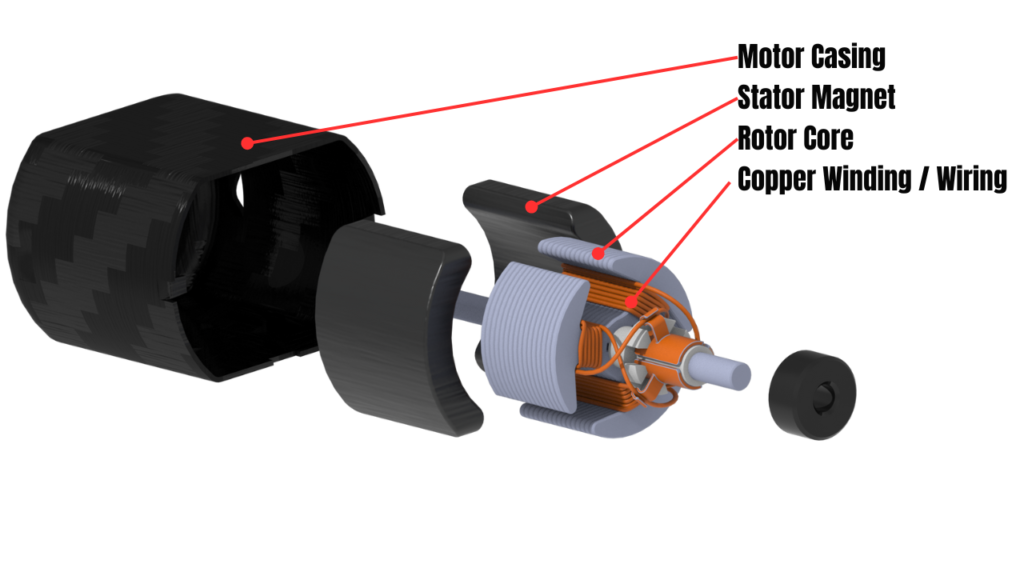
The stationary component of the motor, typically housing the windings or magnets that create the magnetic field. - Rotor:
The rotating part of the motor. It interacts with the stator’s magnetic field to produce the rotating motion. - Electromagnetic Field:
The area of influence generated by the electric current and magnetic materials. Its strength and orientation determine how effectively the motor can produce torque. - Winding: The coils of copper wire wrapped around a core inside the motor. When current passes through these windings, they create the electromagnetic field necessary for producing torque. The number of windings, their arrangement, and the type of wire can all affect a motor’s performance and efficiency.
Understanding these foundations—historical discoveries, core electromagnetic principles, and essential terminology—lays the groundwork for exploring the different types of electric motors, their components, and the factors that make each design uniquely suited to specific applications.
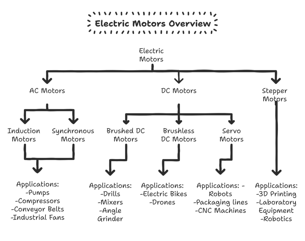
3. Main Types of Electric Motors
Electric motors can be grouped into several broad categories based on how they’re powered and how they generate motion. Below is an overview of the most common types, along with their defining characteristics and typical applications.
Don’t be alarmed! This might look a bit overwhelming, but every design has its own strengths and weaknesses! I will break it down short and simple for now, for you to later learn more about the designs that interest you.
AC Motors - Induction Motor
At the heart of an induction motor is the stator, which houses multiple coils arranged to produce a rotating magnetic field when connected to an AC power source. The rotor, typically a cylindrical arrangement of conductive bars (a “squirrel cage” rotor) or windings (in a “wound rotor” design), sits inside the stator.
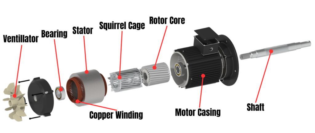
As the stator’s magnetic field rotates, it induces electric current in the squirrel cage—this is the essence of electromagnetic induction. The currents in the cage, in turn, create their own magnetic fields that oppose the stator’s field, generating a force (torque) that sets the rotor spinning.
Very important feature: Induction motors are inherently self-starting, unlike synchronous motors. The rotor in an induction motor always lags slightly behind the rotating magnetic field. This difference in speed, known as “slip,” is essential for current to be induced in the rotor. If the rotor’s speed would match the rotating magnetic field’s speed, there would be no current induced in the cage, so the rotor would start slowing down until the slip difference appears again. Higher load increases slip, allowing the motor to produce the extra torque needed to handle heavier work. It’s expressed as a percentage of the synchronous speed.
Typical slip range: In practical applications, the slip of an induction motor under normal operating conditions usually falls within the 1% to 5% range. This means the actual speed is only slightly slower than the ideal synchronous speed.
Key Advantages of Induction Motors:
Simplicity
No Brushes or Commutator: This design eliminates common wear components, making induction motors inherently low-maintenance.
Straightforward Construction: With fewer parts, manufacturing is more cost-effective at large scales.
- Self-Starting, unlike Synchronous Motors
Durability
Rugged Design: The squirrel-cage rotor can withstand mechanical stresses and thermal variations, ideal for harsh environments.
Long Lifespan: Induction motors often run for years or even decades with minimal service needs, provided they receive basic care like bearing lubrication.
High Reliability
Overload Tolerance: Many induction motors can handle short-term overload conditions without immediate damage.
Operational Stability: They adapt to variations in supply voltage and frequency within reasonable limits, ensuring smooth performance.
Common Variations and Applications
Single-Phase vs. Three-Phase
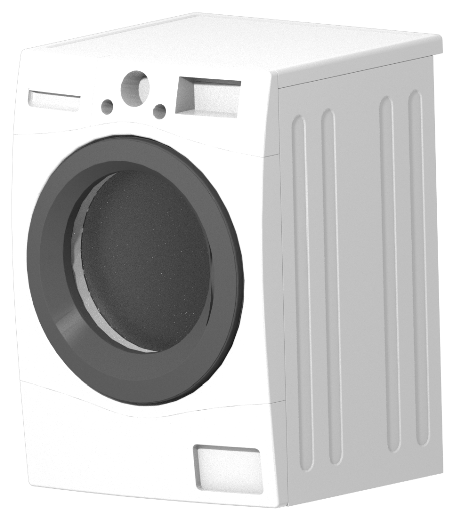
Single-Phase Induction Motors: Often found in household appliances (e.g., washing machines, air conditioners, fans). They rely on additional windings or starting components (like capacitors) to initiate rotation.
Three-Phase Induction Motors: Dominant in industrial settings, powering conveyor belts, heavy machinery, pumps, and compressors. Three-phase motors offer higher efficiency and better torque characteristics than single-phase variants.
Squirrel Cage vs. Wound Rotor
Squirrel Cage: The most common design, featuring bars in the rotor that are cast in a cylinder. It’s robust and largely maintenance-free.
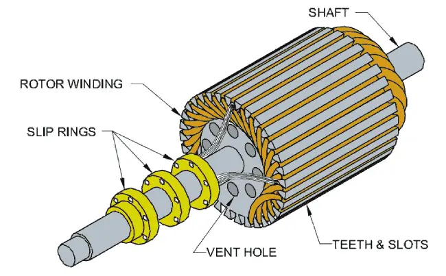
Wound Rotor: The rotor contains windings connected to slip rings, allowing external adjustment of resistance. This design can provide softer starts and adjustable torque but is more complex and expensive.
AC Motors - Synchronous Motors:
While induction motors are more like workhorses of the industry, synchronous motors excel in applications, where precise, constant speed is critical. They operate based on the principle that their rotor spins in exact synchrony (“magnetic locking”) with the stator’s rotating megnetic field.
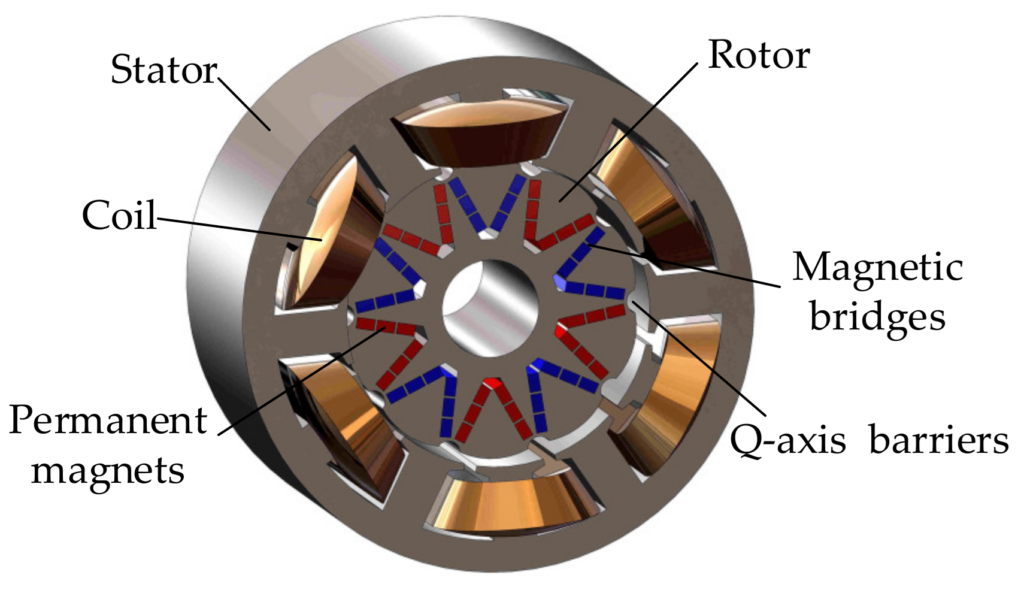
Like all AC motors, synchronous motors use coils in the stator to create a rotating magnetic field when an alternating current is applied. The rotor in a synchronous motor often contains permanent magnets or an electromagnetic winding that requires DC excitation. Once energized, these magnetic poles on the rotor align themselves with the rotating magnetic field from the stator, causing the rotor to spin at the same frequency as the AC input—no slip is required.
Excitation Methods
Permanent Magnet (PM) Synchronous Motors: Use built-in permanent magnets on the rotor. These designs can be very efficient but typically require careful design for start-up.
Electrically Excited Synchronous Motors: The rotor has windings connected to a DC power source via slip rings or brushless exciters, forming electromagnetic poles. This setup allows adjustable excitation levels to control power factor and torque characteristics.
Start-Up Considerations
Traditional synchronous motors need help starting up (unlike induction motors that “self-start”), because the rotor must quickly align with the rotating stator field. Common solutions include:
Separate Starting Mechanism: A smaller induction winding or an external motor might spin the rotor up to near-synchronous speed before excitation is applied.
Reduced Voltage or Variable Frequency Start: In modern systems with sophisticated drives, the frequency of the supply can be ramped up gradually, easing the rotor into synchronization.
Key Advantages of Synchronous Motors
- Constant Speed Under Load
- Synchronous motors maintain a steady rotational speed determined by the AC supply frequency, regardless of load variations (up to the motor’s design limit). This makes them ideal for processes where a precise speed must be held constant, such as in certain conveyor systems, mixers, or material feeds.
- Power Factor Correction
- In some factories and power networks, engineers use a device called a “synchronous condenser.” Essentially, it’s a synchronous motor that runs without driving any machinery. Its main purpose is to adjust the way electricity flows (the “power factor”). By tweaking this power factor, the factory can save on electricity costs and make the overall power supply more stable and efficient.
- Energy Efficiency
- Many synchronous motors, especially modern permanent magnet types, can achieve high efficiencies. Their locked-in operation often translates to minimal energy loss and improved overall performance in demanding tasks.
- High Torque at Low Speeds (in some designs)
- When paired with proper gearboxes or advanced control systems, synchronous motors can deliver high torque at lower operating speeds, beneficial for heavy-duty applications, or high performance vehicles.
To have a deeper understanding in this concept, I recommend the following video, that perfectly demonstrates everything you have to know about the principles of Synchronous Electric Motors:
Typical Applications:
- Many modern EVs use permanent magnet synchronous motors (PMSMs). Their ability to maintain high efficiency over a broad speed range, combined with excellent torque control, makes them ideal for electric cars. This precise speed and torque management also contributes to improved battery utilization and overall performance.
- Some premium washing machines incorporate direct-drive synchronous motors for more accurate drum control. By eliminating belts and pulleys, these motors can provide smoother operation, reduced noise, and better energy efficiency.
- Beyond industrial robots, even certain automated assembly stations or packaging lines use synchronous motors for tasks requiring consistent speed and precise movements. Their built-in capability to run at a set rate without slip helps ensure repeatable, high-quality results.
Why Synchronous Motors?
Despite the added complexity and cost, synchronous motors are indispensable in scenarios where precise speed control and efficient power usage are top priorities. Their ability to hold a constant speed regardless of load and to offset poor power factors in a facility can make them a strategic investment over the long term.
With the rise of advanced control systems (e.g., variable-frequency drives and computerized monitoring), synchronous motors are more accessible and user-friendly than ever. Whether used for continuous manufacturing processes, complex motion control, or improving the electrical efficiency of an entire plant, synchronous motors bring a level of performance and stability unmatched by other AC motor designs.
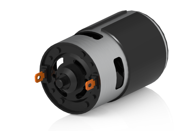
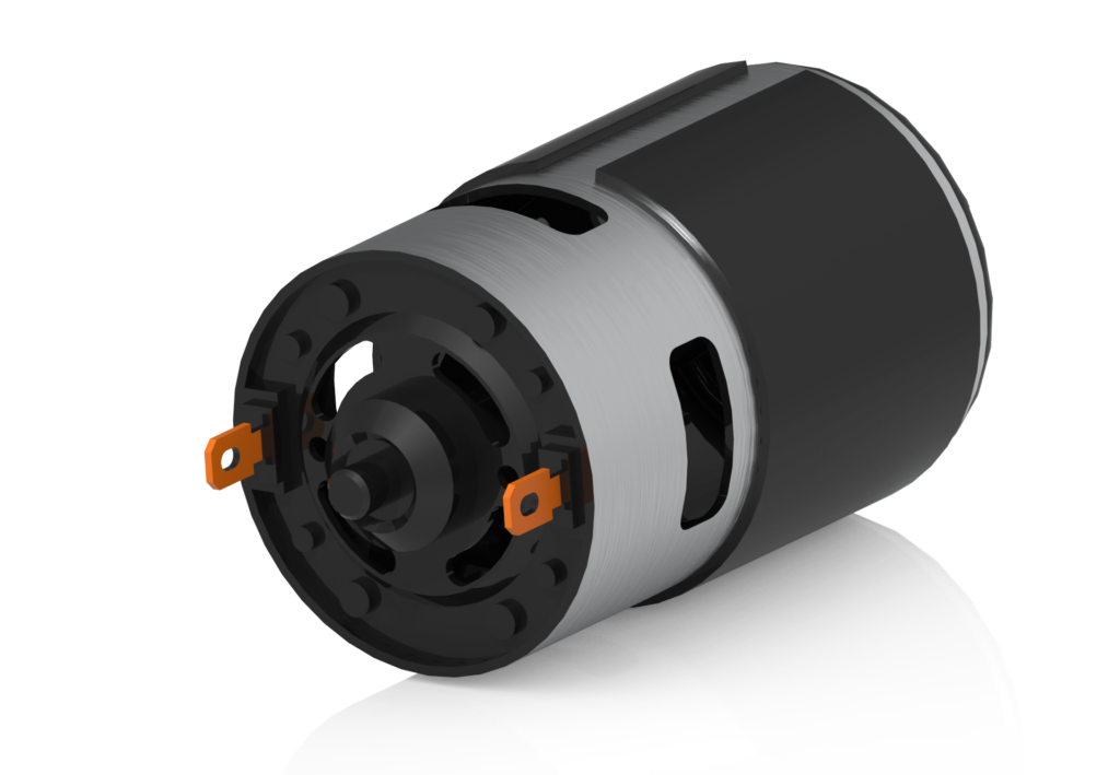
DC Motors - Brushed DC Motors
Brushed DC motors are among the oldest and most straightforward electric motor designs still in widespread use. Despite the popularity of brushless motors in many modern applications, brushed DC motors remain a favorite where simplicity, cost-effectiveness, and easy speed control are high priorities.
Brushed DC motors revolve around a simple idea: an electric current flows through coils (windings) attached to a rotor, creating an electromagnetic field. This field interacts with the stator’s permanent magnets (or sometimes stator windings in larger motors), producing torque and causing the rotor to spin.
A commutator is a segmented copper ring attached to the rotor. It acts as a mechanical switch that reverses the current direction in the rotor windings as the motor turns.
By flipping the current at just the right moment, the commutator ensures the rotor’s magnetic field continuously pushes or pulls against the stator’s field, keeping the motor spinning in one direction.
Small blocks called brushes press against the commutator. Typically made of carbon or a carbon-graphite mix, they carry current from the motor’s external power supply to the spinning commutator.
Over time, friction between the brushes and the commutator can cause wear, which leads to maintenance requirements.
Key Advantages
Simple Control
One of the biggest selling points of brushed DC motors is how easy they are to drive. Adjusting the applied voltage (or current) directly changes the motor’s speed and torque. This simplicity makes them ideal for hobbyists, students, and low-cost industrial setups.
Low Cost
Brushed DC motors are often more affordable to produce than more advanced motor types, thanks to simpler electronics and a long manufacturing history.
Replacement parts (e.g., brushes) are also relatively inexpensive and widely available.
Instantaneous Torque
Brushed DC motors generally provide a good starting torque right from standstill. This characteristic can be helpful in applications where immediate force or lifting power is required at the moment the motor is switched on.
Disadvantages
Brush Wear and Maintenance
Brushes and Commutator: As the motor operates, the brushes make constant contact with the commutator, creating friction and electrical sparks (known as arcing). This leads to gradual brush wear and requires periodic checks or replacements.
Downtime: Frequent use, especially in demanding environments, can shorten the lifespan of brushes, causing more frequent downtime for repairs.
Noise and Sparking
Physical contact between the brushes and commutator can produce noticeable electrical noise and sparks, making brushed DC motors unsuitable for applications where minimal electromagnetic interference (EMI) or absolute cleanliness is a must (for example, certain medical or precision instruments).
Less Efficient at Higher Speeds
Continuous contact, brush friction, and potential heat buildup can reduce overall efficiency, especially as the motor runs at higher speeds.
Typical Applications
Small Household Appliances
Many kitchen gadgets (like blenders and mixers) use brushed DC motors for quick, powerful bursts of action and their straightforward control mechanisms.
Vacuum cleaners also often employ brushed DC motors, taking advantage of their strong torque output.
Toys and Hobby Projects
RC vehicles, small robots, and other hobbyist electronics frequently rely on brushed DC motors. Their low cost and plug-and-play functionality are perfect for projects that require basic motion without advanced control systems.
Engine Starters
Starter motors in cars are classically brushed DC designs because they deliver the high torque needed to crank internal combustion engines from a standstill.
Basic Robotics
Educational and DIY robot kits typically use brushed DC motors, allowing newcomers to learn motion control without the complexity of specialized drivers or feedback sensors.
DC Motors - Brushless DC Motors (BLDC)
Brushless DC (BLDC) motors bring modern electronics and precise control together in a highly efficient and durable package. Unlike brushed DC motors, which rely on physical brushes and a commutator to flip current in the rotor, BLDC motors use “electronic commutation”.
In a typical BLDC motor, permanent magnets are mounted on the rotor, while the stator consists of wound coils distributed around its perimeter. This arrangement can be reversed in some designs, but the fundamental principle is the same: the rotor spins within (or around) a stationary set of coils. Instead of relying on brushes making physical contact with a commutator, BLDC motors depend on an electronic controller to switch current among the stator coils.
Sensors (often Hall sensors) are used to detect the rotor’s position. These sensors send signals to the controller, which then energizes the appropriate coils in sequence. This approach ensures the magnetic fields on the stator are always properly oriented to drive the rotor.
Some BLDC motors operate without Hall sensors, using back-EMF (electromotive force) feedback from the unpowered coils to determine rotor position. Sensorless BLDC designs reduce cost and complexity but require a more advanced controller, especially for smooth starting and low-speed operation.
Most BLDC motors are three-phase, meaning the controller energizes three separate sets of stator coils. This provides smoother torque production and reduces noise compared to single-phase or two-phase systems.
A Hall sensor is a device that detects the presence and magnitude of a magnetic field. It works by measuring changes in voltage caused by the field acting on charge carriers in a thin, semiconductor layer. These voltage variations indicate a magnet’s position, strength, or movement, providing high measurement accuracy.
Key Advantages
High Efficiency
Because there are no brushes (which cause friction and electrical losses), BLDC motors often achieve higher efficiency than their brushed counterparts. They run cooler under load, which is particularly beneficial in battery-dependent applications like drones or electric vehicles where energy conservation is the most essential part.
Longer Lifespan
With no mechanical commutator or brushes to wear out, BLDC motors typically require far less maintenance. The main wear points become bearings and any friction points in the mechanical load, allowing for longer operational life.
Superior Speed and Torque Control
Electronic controllers can finely tune how current is delivered to each stator phase, offering precise control over both speed and torque. This capability is crucial in applications that demand rapid response times (e.g., drones) or steady, controlled speed (e.g., medical devices).
Reduced Electrical Noise
Without brushes, there is no sparking at the commutator surface. This greatly reduces electromagnetic interference (EMI), an important factor for sensitive applications such as in electronics or medical environments.
Typical Applications
Computer Fans
BLDC motors power the cooling fans inside computers and servers, prized for their quiet operation, reliability, and energy efficiency—crucial for machines that run continuously.
Drones and RC Vehicles
Drone propellers and other hobby robotics rely on BLDC motors for their high torque-to-weight ratio and responsiveness, enabling agile flights and rapid accelerations.
Electric Vehicles (EVs)
Older models of EV drivetrains used advanced BLDC motors for relatively high efficiency, good torque characteristics, and minimal maintenance.
Medical Devices
BLDC Motor designs, in special cases, are used in surgical robots, prosthetic equipment, and drug-delivery pumps, where reliability, low vibration, and precise control are critical.
Speed Control and Electronic Commutation
PWM (Pulse Width Modulation)
Most BLDC controllers use PWM signals to adjust the voltage and current supplied to each phase, thereby controlling speed and torque. By varying the duty cycle, the average voltage changes, smoothly ramping motor speed up or down.
Advanced Control Algorithms
Techniques like Field-Oriented Control (FOC) or Trapezoidal Commutation help optimize motor performance, reduce noise, and improve torque handling at varying speeds. These algorithms run on specialized microcontrollers or dedicated driver ICs.
Feedback Systems
Hall-effect sensors or sensorless methods track rotor position and rotational speed, ensuring the right phase is energized at the right time. This feedback loop allows dynamic adaptation to load changes, maintaining consistent speed or torque output.
SERVO Motors
Servo motors are high-performance motors that pair an internal or external feedback sensor (e.g., encoder, resolver, or potentiometer) with precise drive electronics to achieve exceptionally accurate position, speed, and torque control. Technically, any motor—AC or DC—can be operated as a servo motor when combined with the right feedback and closed-loop control.
At the heart of a servo motor is a feedback mechanism continuously measuring the motor’s actual position or speed. A servo drive (sometimes called a servo controller) compares this real-time data against a target command (setpoint). If there is any difference (error), the controller instantly adjusts the power supplied to the motor to correct it.
- Common sensor types include:
- Rotary Encoders: Digital or optical devices providing precise pulse counts per revolution.
- Resolvers: Electromagnetic sensors generating analog signals that correspond to shaft position.
- Potentiometers: Mostly used in simpler or low-cost servo designs; convert rotary motion into variable resistance, giving a rough positional reading.
The choice of sensor depends on the accuracy, speed range, and environmental conditions required by the application.
Error Correction
A PID (Proportional-Integral-Derivative) or other control algorithm in the servo drive calculates how much power the motor needs to correct any deviation from the setpoint. This real-time loop ensures extremely fine control over motion.
Key Advantages
Precision
Servo motors excel in tasks demanding tight positional accuracy. In a robotic arm, for example, a servo can move to a specific angle (or linear position, if it’s driving a leadscrew) repeatedly with minimal error.
Closed-Loop Control
The constant feedback loop means servo systems can respond to disturbances or changes in load almost instantly, ensuring stable operation even under variable conditions.
This control also enables higher torque at low speeds compared to some open-loop systems, as the servo drive automatically adjusts current to maintain the desired position or speed.
High Speed and Torque Bandwidth
Servo motors can ramp up speed or torque in a fraction of a second, making them suitable for fast, dynamic operations—like pick-and-place machinery in manufacturing lines.
Smooth Performance
Because the system continuously corrects errors, servo motors generally operate with minimal vibration or overshoot, providing fluid motion across a wide speed range.
Typical Applications
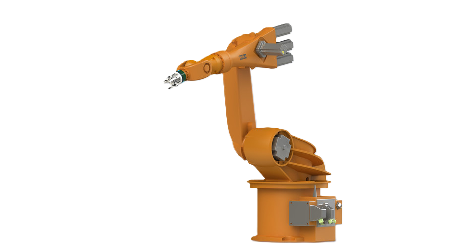
Robotics and Automation
Robotic arms, automated production lines, and pick-and-place machines rely on servo systems for repeatable, precise motion. Any small error in a robot’s joint angle can cause significant positioning issues, making servo feedback essential.
- CNC (Computer Numerical Control) Machinery
Servo-driven CNC mills, lathes, and routers achieve accurate cuts and finishes. The motor adjusts rapidly to maintain the programmed toolpath despite cutting forces or material inconsistencies.
Camera Gimbals and Stabilizers
Servo motors, combined with advanced control algorithms, help keep cameras stable and level even if the gimbal’s base moves around (e.g., on a drone or a moving vehicle).
3D Printers and Precision Manufacturing
While many 3D printers use stepper motors, some high-end models feature servos for better responsiveness and error correction—vital for complex or ultra-precise prints.
Packaging and Labeling Systems
High-speed automated packaging lines use servos to precisely position products, apply labels, or fill containers with minimal waste.
Disadvantages
Higher Complexity and Cost
Because servo systems require dedicated drives, sensors, and control loops, they are more complex and expensive than simpler motor setups.
Additional wiring, programming, and tuning (e.g., adjusting PID parameters) can increase design and installation costs.
Sensitivity to Configuration
Achieving optimal performance often involves fine-tuning the control parameters. Incorrect settings can result in overshoot, instability, or oscillations.
Maintenance of sensors and calibration is crucial in harsh environments to preserve accuracy.
Potential for Overload
While servos handle short bursts of overload well, continuous heavy loads can cause thermal issues. Proper sizing (motor, drive, and cooling) is essential to avoid overheating and motor damage.
Variations in Servo Motor Technology
AC Servo Motors: Operate on AC power, often with three-phase stator windings and permanent magnets on the rotor. They tend to be more robust at high speeds and suitable for industrial tasks.
DC Servo Motors: Rely on DC power (brushed or brushless). Though simpler in some cases, DC servos often require careful heat management under sustained load.
Direct Drive Servos: Eliminate gearboxes or belts, directly coupling the motor’s shaft to the load for reduced mechanical backlash and improved precision.
4. Conclusions
Electric motors are the backbone of modern technology, powering countless devices and processes—from household gadgets and industrial machinery to electric vehicles and cutting-edge robotics. By understanding how they generate motion, along with the unique characteristics of each main motor type, you can make more informed choices for any application that relies on mechanical motion.
However, the world of electric motors extends far beyond the categories we’ve highlighted here. There are numerous specialized designs, advanced control methods, and performance-enhancing features worth exploring. Whether you’re interested in high-efficiency motors, ultra-precise positioning systems, or emerging “smart motor” technologies, there’s always more to learn and discover.
How Electric Motors Work
© Copyright 2025 - All Rights Reserved